Hoelz Lab: Publications
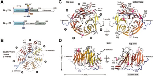
Figure 1 The structure of the N-terminal domain of human Nup214. (A) Domain structure of Nup214 and Nup159. The construct used for crystallization is boxed red and two phosphorylation sites of the NTD are indicated. Residues observed in the crystal structures are boxed in blue. (B) Schematic representation of the NTD structure. The blades of the β-propeller are labeled from 1 to 7. The CTE is shown in blue and beta-strands forming the double-Velcro closure are indicated with an asterix. (C) Ribbon representation of the NTD structure. A 180˚-rotated view is shown on the right. As a reference, the strands of blade 3 are labeled A-D. The blades of the β-propeller and the CTE are labeled as in B. The helical insertions are shown in pink. (D) Ribbon representation of side views of the structure of the NTD. The view on the right is rotated by 180˚.

Napetschnig, J., Blobel, G., Hoelz, A. (2007). Proc. Natl. Acad. Sci. USA 104, 1783-1788.
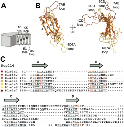
Figure 2 Superposition of the NTD β-propeller blades. (A) Schematic drawing of a β-propeller fold indicating the β-strands and loops of one β-propeller blade. (B) Coil representation of the structural alignment of the seven blades of the β-propeller. Blades are colored as in Figure 1. As a reference, the C atoms of blade 2 are shown as orange spheres. A 90˚-rotated view is shown on the right. (C) Structure-based sequence alignment of the blades. The -strands are indicated above the sequence. Similar residues are shown in red and residues of each blade that participate in β-sheet hydrogen bonds are underlined in grey.
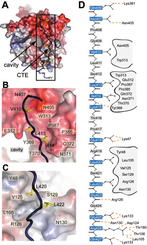
Figure 3 CTE binding to the bottom face of the β-propeller. (A) The surface of the Nup214 β-propeller is colored according to the electrostatic potential from -10 kBT (red) to +10 kBT (blue). The CTE is shown in blue coil representation with the side chains in ball and stick representation. The black box indicates the region magnified in D. (B) Hydrophobic interactions of CTE residues Val410, Leu413 and Leu414 (yellow) and (C) Leu420 and Leu422 (yellow) with residues of the β-propeller. Hydrophobic pocket-forming residues are shown in grey. The surface of the β-propeller is colored as in A. (D) Schematic representation of the contacts between the β-propeller and the CTE. Hydrogen and ionic bonds are indicated by orange dashed lines and van der Waals contacts with grey grooves.
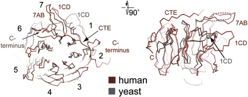
Figure 4 Structural comparison of the NTD of the human Nup214 and its yeast homologue Nup159. (A) C-trace of a structural superposition of the Nup214 NTD (ruby) and the Nup159 β-propeller (grey).
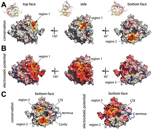
Figure 5 Conserved features of the NTD. (A) Surface representation showing conservation of residues within higher eukaryotes. The conserved surface is shaded from grey (< 70% identity) to red (100% identity) according to the alignment in Figure S3. (B) Electrostatic potential of the NTD surface (colored as in Fig 3A). (C) Surface representation of the bottom face of the Nup2141-405 showing the surface conservation within higher eukaryotes (left view) and electrostatic potential (right view). The C-trace of the CTE is shown in a blue coil representation.
Figures from the paper:
Coordinates:
Abstract:
The mammalian nuclear pore complex (NPC) is an approximately 120-MDa proteinaceous assembly consisting of approximately 30 proteins and is the sole gate in the nuclear envelope. The human protooncogene Nup214 was first identified as a target for chromosomal translocation involved in leukemogenesis. Nup214 is located on the cytoplasmic face of the NPC and is implicated in anchoring the cytoplasmic filaments of the NPC and recruiting the RNA helicase Ddx19. Here, we present the crystal structure of the human Nup214 N-terminal domain at 1.65-A resolution. The structure reveals a seven-bladed beta-propeller followed by a 30-residue C-terminal extended peptide segment, which folds back onto the beta-propeller and binds to its bottom face. The beta-propeller repeats lack any recognizable sequence motif and are distinguished by extensive insertions between the canonical beta-strands. We propose a mechanism by which the C-terminal peptide extension is involved in NPC assembly.
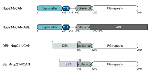
Figure S1. Domain structure of Nup214/CAN and Nup214/CAN fusions implicated in leukemogenesis.
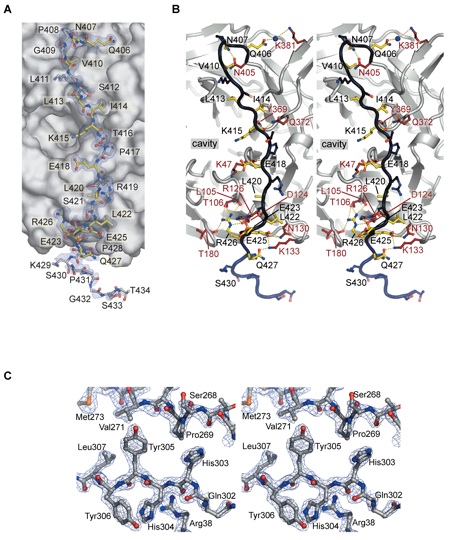
Figure S2. (A) A simulated-annealed 2|Fo|-|Fc| electron density map, contoured at 1.0, is shown for the CTE (ball and stick representation). Residues of the β-propeller domain forming hydrogen bonds with the CTE are colored in ruby, CTE residues that interact with the β-propeller domain are shown in yellow, and CTE residues facing away from the interface are colored blue. (B) A stereo-view of the interactions of the CTE with the Nup214/CAN β-propeller domain. The CTE-residues are colored as in (A). (C) Stereo-view of a representative region of the experimental electron density map contoured at 2.0 (blue). The final Nup214/CAN NTD model is shown in ball-and-stick format.
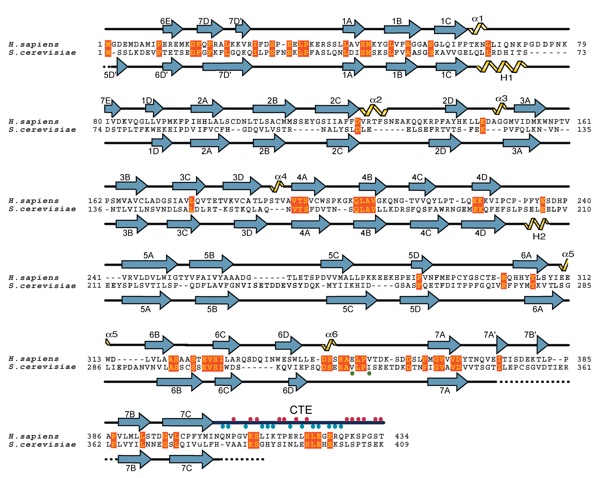
Figure S3. Structure-based alignment of the primary sequence of the human Nup214/CAN NTD and the yeast Nup159 β-propeller domain. Secondary structure elements are indicated above (Nup214/CAN) and below (Nup159) the aligned sequences. Residues of the CTE that either interact with the β-propeller domain (blue dots) or face away from the interface (red dots) are indicated. The positions of the yeast Nup159 mutations V323E and I326E, which disrupt binding of the yeast Dbp5 helicase are indicated with a green dot. Blue, alpha-sheets; black, coil regions; yellow, alpha-helices; black dots, disordered regions.
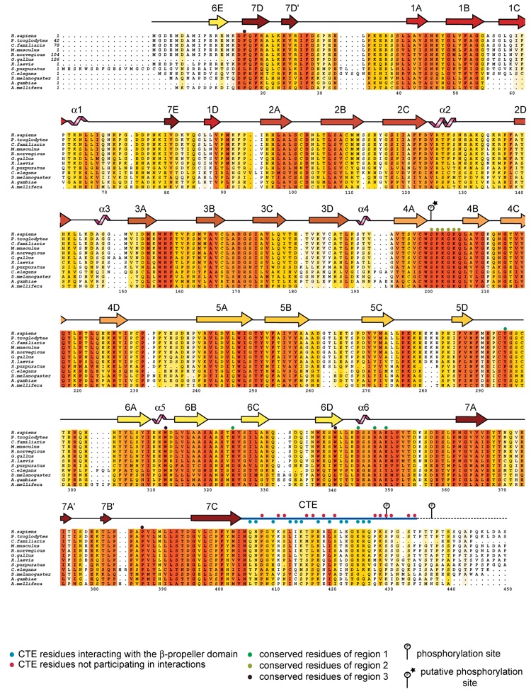
Figure S4. Sequence alignment of Nup214/CAN NTD within higher eukaryotes. Alignment of Nup214/CAN homologues. The secondary structure is indicated above the sequence as arrows (-strands), black lines (coil regions) and pink helices (-helices). The numbering below the alignment is relative to the human Nup214/CAN sequence. The overall sequence conservation at each position is shaded in a color gradient from white (<40% identity) to red (100% identity). Residues of region 1, region 2 and region 3 as well as phosphorylation sites of the Nup214/CAN NTD are indicated above the sequences; a putative phosphorylation site is marked with an asterix.
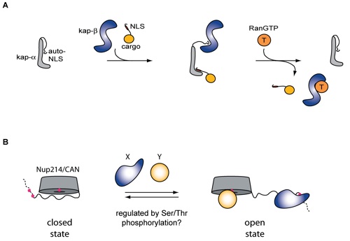
Figure S5. (A) Schematic representation of the regulation of the mobile phase of nuclear-cytoplasmic transport (as discussed in the text). (B) Hypothetical model illustrating the role of auto-NLS-like peptide segments, such as the CTE of Nup214/CAN, in nup interactions.

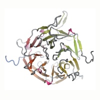
Crystal structure of the N-terminal domain of the human protooncogene Nup214/CAN.
California Institute of Technology
Division of Chemistry & Chemical Engineering
1200 E. California Blvd.
Pasadena, CA 91125-7200
© Copyright Hoelz Laboratory
